Ready when you are.
A brand-new website, a network rebuild, a custom board or a tricky hardware fault, drop us a line and we'll respond within one working day. Quotes are free.
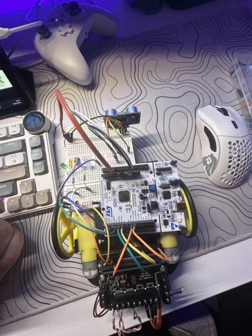
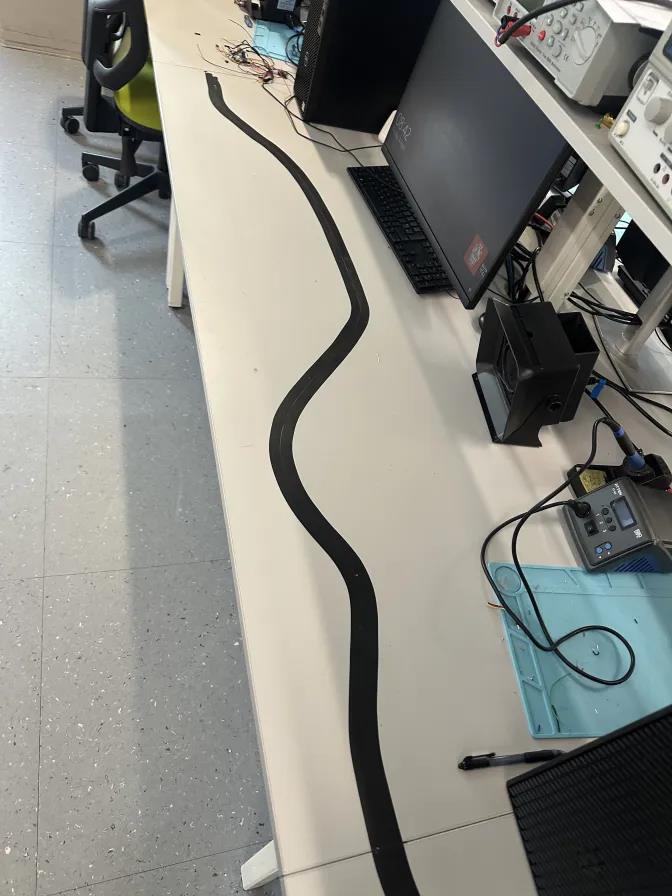
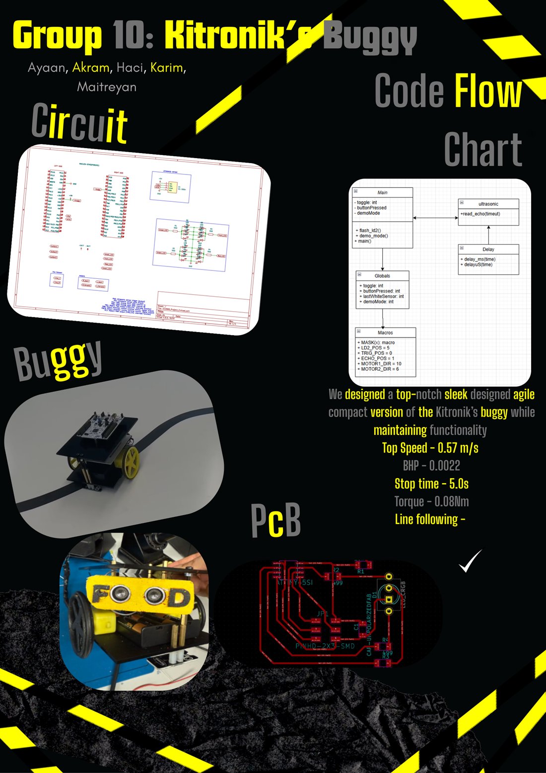
info@nyna.co.ukA line-following robot buggy built on the STM32 NUCLEO-F091RC in bare-metal C, a Kitronik chassis driven through an L298 on PWM, steering from two LDR line sensors, stopping for obstacles on an ultrasonic sensor, and signalling with indicator, brake and headlight LEDs. A five-person Embedded Systems project at Royal Holloway, where I led testing, debugging, calibration and integration.
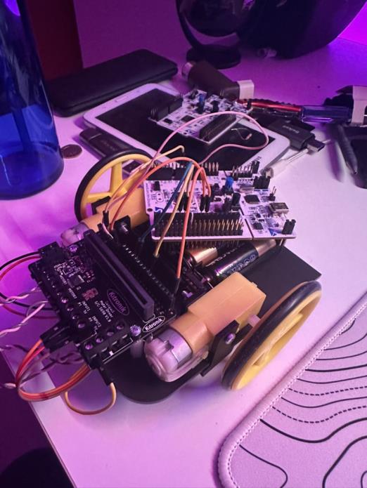
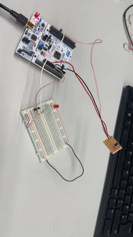
Two downward-facing LDRs are read through the F091's ADC (PA4 and PB0) and thresholded to digital. The buggy steers by cutting PWM to whichever motor sits over the line, driving differential speed on the L298 through Timer 3. An HC-SR04 ultrasonic sensor (trigger PA0, echo PA1) measures range as echo / 58; inside a set distance the buggy halts, lights its hazard LEDs and crawls until the obstacle clears. Mode changes run off EXTI button interrupts, and a millisecond timer gives a five-second stop-and-resume. Amber corner LEDs flash as indicators, rear LEDs act as brake lights and white LEDs run as headlights.
In a team of five, I owned testing, debugging and calibration, and the integration that brought the subsystems together.
// Read both LDRs on the ADC, threshold to digital
ldr1 = adc_read(CH4);              // PA4
ldr2 = adc_read(CH8);              // PB0
uint8_t a = (ldr1/4095.0f >= 0.5f);
uint8_t b = (ldr2/4095.0f >= 0.5f);

uint32_t base = 840;               // ~0.2 m/s
if (a && !b)      { L = base;   R = 0;    }   // bear left
else if (!a && b) { L = 0;      R = base; }   // bear right
else              { L = base/2; R = base/2; } // on the line
TIM3->CCR1 = L;  TIM3->CCR2 = R;   // drive the L298
TRIG_LOW;  delayuS(2);
TRIG_HIGH; delayuS(10); TRIG_LOW;          // 10 us pulse
float distance = read_echo(400000) / 58.0f;

if (distance <= 2.5f) {                     // obstacle ahead
    LED_D2_ON; LED_D3_ON; LED_D4_ON;        // hazard lights
    TIM3->CCR1 = 0; TIM3->CCR2 = 0;         // full stop
    while (read_echo(400000)/58.0f <= 2.5f) // crawl until clear
        { TIM3->CCR1 = 300; TIM3->CCR2 = 300; delay_ms(50); }
}
A brand-new website, a network rebuild, a custom board or a tricky hardware fault, drop us a line and we'll respond within one working day. Quotes are free.
info@nyna.co.uk